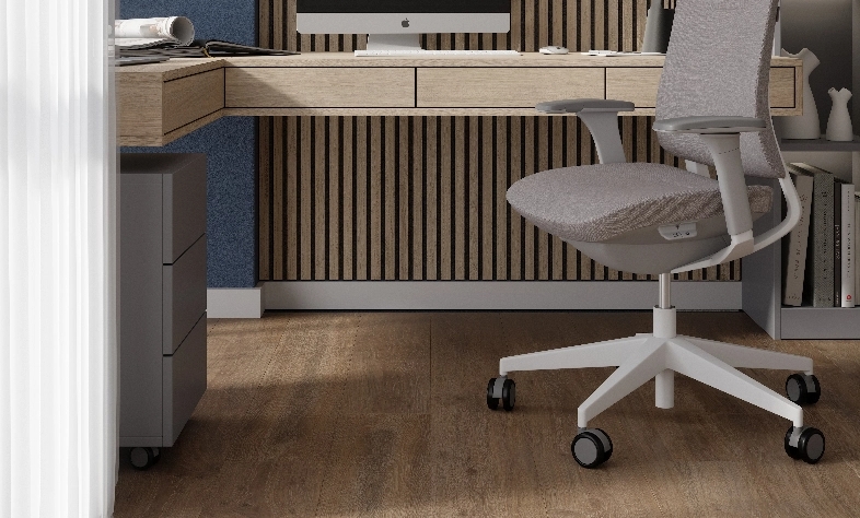
FAVOURITE FOR EVERYDAY LIVING
LAMINATE
FLOORING
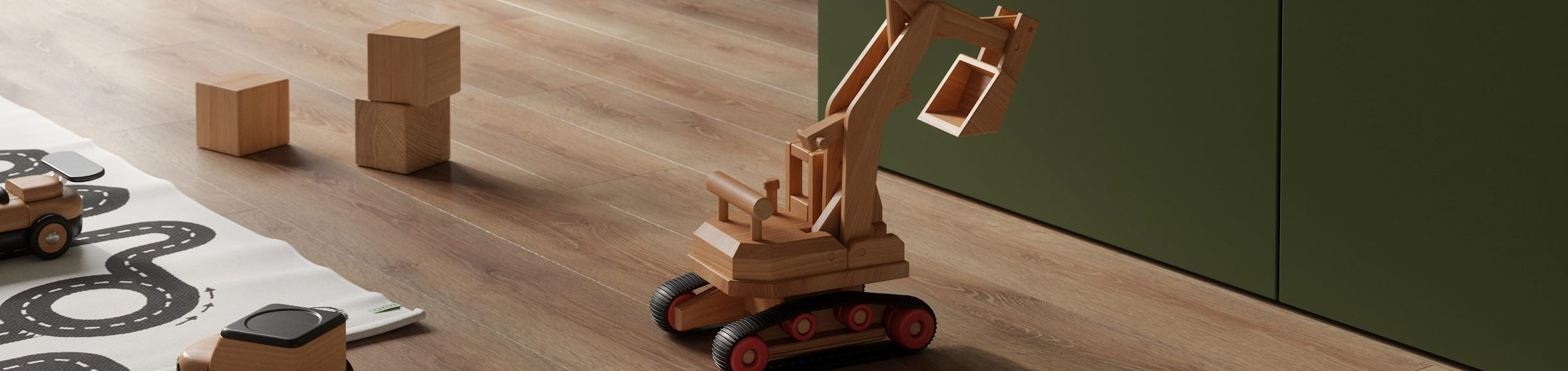
OPTIMIZED WOOD
FIBER TECHNOLOGY
Time on Your Side:
Up to 8 hours of protection against standing water.

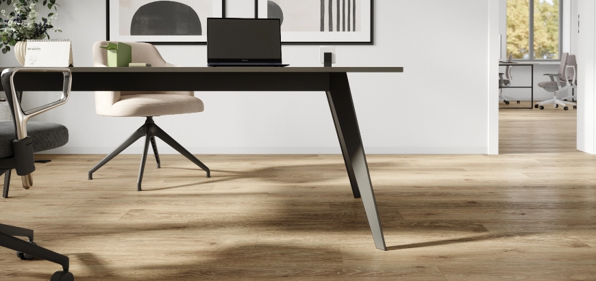
AUTHENTIC LOOK
AND FEEL
LIGHT
RESISTANT
DIY-FRIENDLY
INSTALLATION
HYGIENIC* AND
EASY-TO-CLEAN SURFACE
UTILIZATION
CLASS 32
* Tested germs: Staphylococcus aureus
CLASSIC LAMINATE
COLLECTION